
















BASIC KNOWLEDGE What is power factor? Basics, formula, and calculation explanation
Related Vendors


A good power factor promises high system capacity for industrial sites and equipment reliability for manufacturers. In the beginning, power factors can be either good or poor. A good power factor indicates better utilization of power by the AC system, while a poor power factor indicates power wastage. If the power factor is poor beyond acceptable levels, engineers design and add components or networks to improve it.

The origins of power factor trace back to multiple events. Some claim that a German physicist, Ernst Werner von Siemens, deduced it and named it “Siemens Power Factor”. Other sources trace it back to Serbian-American engineer, physicist, and inventor Michael Pupin. More than an origin story, power factor is a criterion that industrial sites and electronic product sellers have to meet.
Power Factor Definition
Power factor is defined as the ratio of the power that does useful work to the actual power drawn from the supply. By calculating power factor, engineers can determine how effectively an electrical/electronic infrastructure works. In short, the power factor shows how much current actually performs its operation and how much is wasted.
What are three different types of AC power?
DC circuits supply constant currents and voltages from the source to the load. The story of AC is different. AC circuits supply alternating currents and voltages from the source to the load. This is why AC systems have a frequency, commonly 50 Hz in Europe and most of Asia and 60 Hz in the U.S. and the rest of the Americas, with some parts of South Korea and Japan. The frequency means that AC power completes 50/60 cycles per second.
One cycle completes when currents/voltages rise from zero to peak and reverse from peak to zero again. About 50/60 times per second. That’s how fast it is. But not 100% of the power reaches from the source to the load. The fluctuating nature of AC makes them lose (and use) some portion of the power. In addition, currents and voltages are not travelling at the same speed. They can be in-phase or out-of-phase with each other. This gives rise to the concept of three different powers in AC circuits: active, reactive, and apparent power.
Active power (Useful work): Also known as true power, working power, real power, or average power, active power is the amount of energy spent on doing useful work in an AC system. The useful work in the AC system corresponds to lighting, switching, computation, mechanical action, movement, heating, or any other purpose the system is deployed for.
In simple words, it represents the amount of power dissipated by the system. The magnitude of active power shows up on the wattmeter in watts (W) or kilowatts (kW).
As a general formula, power is the product of voltage and current flowing in a system.
In AC circuits, active power (P) is the product of root mean square (RMS) voltage and current. When it comes to RMS, phase angles are also considered in the calculation.
All these equations are useful in deducing the power factor formula.
Reactive power (Wasted): The second type, reactive power (Q), is defined as the power that oscillates back and forth between the source (generator) and load, due to the action of the reactive components of the circuit, which are capacitors and inductors.
It’s a well-known fact that capacitors store electric charge in the form of an electric field and release it back. Similarly, inductors store energy in the form of a magnetic field and release it later. The storing/releasing action gives rise to reactive power, which is always absorbed/returned to the circuit.
This means that reactive power does no useful work, but rather than storing/releasing. Hence, it’s not expressed in watts. This is why reactive power is also known as wattless power or imaginary power. Instead, reactive power is expressed in volt-amperes-reactive (VAR) or kilovolt-amperes-reactive (kVAR).
Reactive power (Q) is the product of root-mean-square (RMS) voltage and current multiplied by the sine of the phase angle.
It’s important to note that reactive power is undesirable in high amounts. In general, reactive power mostly stays lower than active power.
Apparent power: Apparent power is the total power existing in an AC circuit, including the power flowing between the components and the power consumed to perform tasks. In simple terms, apparent power is the total power supplied by the source.
It is expressed in volt-amperes (VA) or kilovolt-amperes (kVA). So, it can be measured by voltmeters or ammeters and calculated on paper by engineers.
Apparent power (S) is the product of root-mean-square (RMS) voltage and current.
Some companies draw an analogy between the power factor and a glass of beer. For example, you pay $50 for a glass of cold drink. The actual liquid you can drink correlates to the actual power, while liquid lost as froth is just a show-off/decoration; you can’t actually have it. That correlates to wasted power.
A glass having a little to drink below a heavy froth is a waste of money. That’s a poor power factor. Similarly, the opposite: a glass with little froth, followed by enough liquid underneath, correlates to a good power factor. You got slightly less for what you paid.
Power triangle
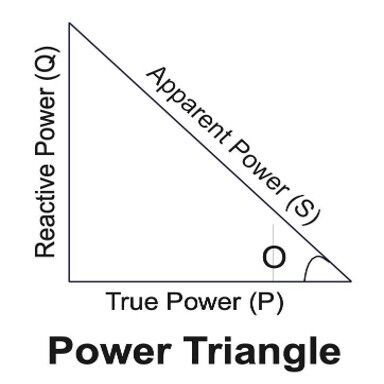
The power triangle is drawn to represent the physical relationship between all three types of AC power: active, reactive, and apparent. In simple terms, the power triangle explains how to calculate power factor.
According to the Pythagorean theorem, in a right-angled triangle,
In a power triangle, true/active power (P) represents the base, reactive power (Q) represents the perpendicular, and apparent power (S) represents the hypotenuse.
Applying the Pythagorean theorem to the power triangle,
By equations 1, 2, and 3,
Shifting roots,
Taking voltages and currents common in the root side,
Expanding squares in trigonometric functions,
According to the trigonometric relationship between sine and cosine squares,
Applying the same to the equation,
Left-hand side (LHS) = Right-hand side (RHS)
This—the power triangle—proves that apparent power is the vector sum of active and reactive powers.
Power factor formula and equation
By understanding the three types of AC power and their power triangle, the power factor definition is modified: Power factor is the ratio between active power absorbed by the load and apparent power supplied by the source.
The power factor formula becomes the ratio of active and apparent powers.
From equations 1 and 3,
Voltage × current is power in watts only.
By the power factor formula, we can conclude that power factor is just a number: a dimensionless quantity ranging between zero and one.
Poor power factor: A power factor near zero correlates to poor performance of the AC system. It means that a large share of current moves back and forth between the source and load, without performing any useful function.
For industries, poor power factor incurs utility bill penalties. The solution is to use bigger cables, high-rated equipment, and implement power factor correction (PFC) strategies.
Good power factor: A higher power factor near 1 indicates that current does all the useful work in the system. It means the AC system performs well.
What is the power factor of a resistive load?
A pure resistive load is a circuit in which there are only resistances with the supply voltage. A group of resistors connected in series or parallel, forming a net resistance, is also a resistive circuit. It doesn’t have any other components.
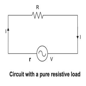
As currents and voltages don’t lag or lead each other, they’re in phase.
The phase angle is zero.
Φ is 0
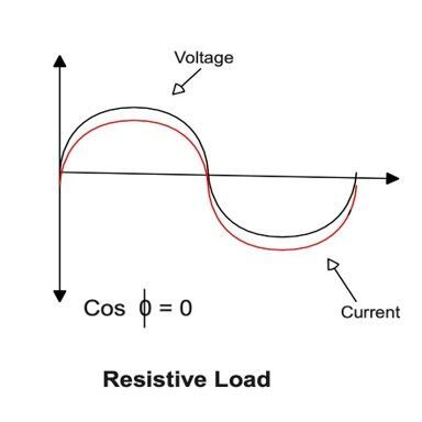
Power factor = Cos Φ
Power factor = Cos (0)
Power factor = 1
If you’re wondering what is the power factor of a resistive load, the answer is unity ~ 1.
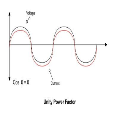
Examples of resistive loads are incandescent bulbs, filament lamps, soldering irons, and kitchen appliances like lightbulbs, toasters, ovens, and space heaters.
Leading power factor
A pure capacitive load is an AC circuit in which a capacitor is the load to the supply voltage. It doesn’t have any other components.
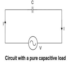
In purely capacitive loads, currents lead voltages by 90 degrees. This happens because capacitors store energy as charge (q). They store the charge during the charging process and release it back to the circuit when discharged.
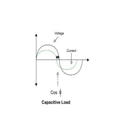
Capacitive loads have a leading power factor because voltages come after currents.
Examples of capacitive loads include capacitor banks, overhead/buried/underground cables, transmission lines, audio equipment, RF devices, and medical equipment.
Lagging power factor
In a purely inductive load, the inductor is the load for the AC supply. It doesn’t have any other components.
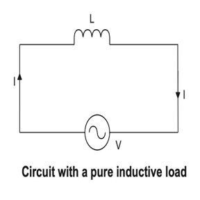
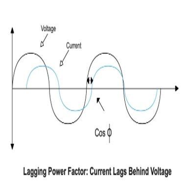
Currents lag 90 degrees behind voltages. This is because inductors store energy in their magnetic field. They oppose changes in current flow by either storing or releasing magnetic fields. All of this causes the current to lag the voltage.
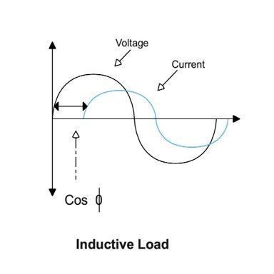
Inductive loads have a lagging power factor because currents chase voltages.
Examples of inductive loads include transformers, motors, relays, solenoids, induction furnaces, and consumer home appliances like fans, refrigerators, air conditioners, and washing machines.
| Type of load | Power factor |
| Resistive | Unity |
| Capacitive | Leading |
| Inductive | Lagging |
How to calculate power factor?
It’s important to note that commercial electronic loads cannot be purely resistive (R), capacitive (C), or inductive (L). Circuits are a combination of LC, RC, and LCR with dozens of electronic components like transistors, diodes, transformers, and many more. The section shares three working examples to explain how to calculate power factor.
Problem 1: A 230 V, 50 Hz AC power system contains an inductor of 50 mH with a reactance of 15.7 Ω and a circuit current of 5A. The wattmeter shows a power reading of 1081 W. Calculate the power factor and phase angle.
Solution:
Power factor = 0.94 (Lagging)
To calculate the phase angle, take the inverse cosine from here.
As it’s an inductive load, the current lags by 19.95 degrees, approximately 20 degrees behind the voltage.
Problem 2: Calculate the power factor and phase angle of a single-phase AC motor running on a 230 V, 50 Hz AC supply. The current flowing through the circuit is 9 A, and the wattmeter shows a reading of 1500 W.
Solution: Let’s first calculate apparent power (S) because it leaves the source.
Given,
Active power as shown on the wattmeter.
P = 1500 W
By the power factor formula, divide active power by apparent power.
Power factor = 1500/2070
Power factor = 0.724 (Lagging)
To calculate the phase angle, use the formula for power factor,
Cos = 0.724 Φ
Inverse the cosine function.
Φ = Cos-1(0.724)
The inverse cosine can be calculated here.
Φ = 43.61 degrees
As the motor is an inductive load, the current lags 43.61 degrees behind the voltage.
Problem 3: Calculate the power factor and phase angle of a single-phase AC capacitor bank running on a 230 V, 50 Hz AC supply. The current flowing through the circuit is 7 A, and the wattmeter shows a reading of 1100 W.
Solution: Let’s first calculate apparent power (S) because it leaves the source.
Given,
Active power as shown on the wattmeter.
P = 1100 W
By the formula for power factor, divide active power by apparent power.
Power factor = 1100/1610
Power factor = 0.683 (Leading)
By the power factor formula,
Cos Φ = 0.683
Inverse the cosine function.
Φ = Cos-1 (0.683)
The inverse cosine can be calculated here.
Φ = 46.92 degrees
As it’s a capacitive load, current leads the voltage by 46.92 degrees.
What can a good power factor lead to?
A good power factor should be a minimum of 0.9 and a maximum of 1. However, real-world power factors usually range between 0.6 and 0.8. These are uncorrected values. Once power factors are improved, engineers can achieve the following benefits.
High efficiency: When power isn’t wasted in the system, it does all the useful work. Otherwise, wasted power overloads the electrical power system.
Lower bills: Utility companies charge commercial sites for a power factor lower than 0.9-0.95. This means that higher power factors cut down on penalties.
Lower losses: High reactive power, or wasted power, results in resistive losses. As a result, equipment starts to heat up. High values can function as a power factor saver, resulting in better thermal management of power systems.
Lower current flow: A high power factor reduces the amount of [reactive] current flow in a power system, which in turn lowers voltage drop across cables, windings, feeders, and all other components. This results in better voltage regulation.
Supports miniaturization: Even the power factor of power supply units of phones and computers must be high. This is because a higher power factor enables efficient use of smaller equipment and fewer cables.
High efficiency: Due to poor power factors and thermal stress, inductive loads and power converters overheat and become inoperative over time. A high power factor reduces power losses. This means systems act like a power factor saver, extending equipment lifespan.
Continuous operation: As a high power factor reduces power wastage, equipment can function for longer without any crashes or downtime.
Enhanced system capacity: A high power factor improves the overall capacity of the system to generate and deliver more power, handle more loads, and satisfy more demands. In short, this means more electrical workload at the same power level.
Lower footprint: As less power is wasted, a high power factor further leads to industries burning less fuel to deliver the same amount of energy. As a result, a lower footprint becomes an indirect impact.
How to calculate power factor practically?
The conventional method for a power factor calculator is to use multiple instruments: a wattmeter, an ammeter, and a voltmeter. The power measured by the wattmeter is divided by the voltage measured by the voltmeter and the current measured by the ammeter.
Calculating values using the equation of power factor can be time-consuming and expensive to implement because it requires the collaboration of multiple measuring instruments. Another quick answer for how to compute power factor is to use an online power factor calculator. Several sites have developed such online power factor calculators.
The industry relies on the fastest method for how to find power factor, which is to use an electrodynamic measuring instrument known as a power meter. This instrument can be connected to an AC power system, where it measures voltages and currents. Then, it deduces active and reactive power to display the power factor on the dial screen.
The commercial picture
Harmonics are among the main reasons that contribute to a poor power factor. They are high-frequency components found in AC/DC output current and voltage waveforms. By nature, all AC or voltage waveforms must be sinusoidal. Harmonics reduce this sinusoidal wave to a non-sinusoidal structure.
The main reason for harmonics is non-linear loads. In today’s world, 70% of all loads are nonlinear, like lights, LEDs, computer-based devices, and televisions. The fluctuating nature of such loads draws currents in pulses, distorting the system output. As a result, harmonics tend to overheat the device and create noise.
In the true sense, Cos is the power factor formula of a linear load in a single-phase system, but grid and industrial power rely on three-phase systems. Power factor calculations of three-phase systems include the square root of three at each step.
For non-linear load-based distortion, the displacement factor is taken into consideration. It accounts for harmonic currents and voltages present due to nonlinear loads.
The equation of power factor now becomes Cos .
The concept of power factors extends beyond AC into DC because no commercial system is purely AC or DC. At each stage, multiple conversion stages are required: AC to DC, DC to DC, DC to AC, and even AC to AC. Wherever AC is present, power factors must be considered and corrected.
References
- https://eshop.se.com/in/blog/post/difference-between-active-power-reactive-power-and-apparent-power.html#1
- https://amandaenergy.com.au/news/attention-all-large-use-electricity-customers-what-is-your-power-factor/
- https://techweb.rohm.com/product/circuit-design/electric-circuit-design/20887/
- https://www.digikey.com/en/maker/tutorials/2024/what-is-power-factor-how-is-it-calculated-and-why-its-important
- https://reload.tools/blogs/lingo/power-factor
- http://energyefficiencygrp.com/power-factor-correction/history-of-power-factor-correction/
- https://www.monolithicpower.com/en/learning/mpscholar/ac-power/power-factor/causes-and-effects-of-low-power-factor?srsltid=AfmBOoqwaaI0a1faDIRUhChQApQsQ1koyeV5T-CLj8tnS6AvaHSTOP70
(ID:51004379)

