
















RECTIFIER Off-time control of the vienna rectifier
Related Vendors


In this article, the author shows how to simulate and stabilize a Vienna rectifier without sensing the high-voltage rail. This so-called predictive control is popular in single-phase power factor correction (PFC) circuits and lends itself well to controlling the power switches of a three-phase PFC. Learn how LTspice simulations associated with SIMPLIS can help closing the loop for a stable operation of the converter.

In the previous article "Average models are versatile design companions", I have shown how the 3-phase Vienna rectifier could be stabilized by resorting to average models based on the PWM switch model 1). The compensation strategy was adapted based on the ac responses of the loops, involving sinusoidal pulse-width modulation (SPWM).
If the Vienna rectifier lends itself well to different types of control, it is perhaps less known that a predictive control law can also be used to actuate the power switches. A paper published in 2005 2) shows how the Vienna converter could be controlled in a simple analogue way, without resorting to a complex control structure. This article explains the basics of the technique and illustrates operating results via simulations in LTspice and SIMPLIS.
Power factor correction without high-voltage sensing
Work in this domain has been pioneered by J. Gegner with a paper 3) he co-authored in 1996. In this document, the author introduces a control technique based on peak inductor current sensing applied to a power factor correction converter (PFC) operating in continuous conduction mode (CCM). The experimental circuit is based around the popular UC2843 and does not resort to a multiplier for generating the inductor current setpoint. Rather, it uses an external ramp superimposed to the instantaneous power switch current to generate the voltage feeding the current-sense comparator. In this approach, there is no input voltage sensing which was very original at the time.
Two years later, Sam Ben-Yaakov published a paper 4) in which he also showed how to emulate a resistive input, again, without sensing the high-voltage input. The principle of operations is described in Figure 1. By programming the off-time duty ratio such as:
, it can be shown that the current absorbed by the converter is sinusoidal. The error voltage Ve controls the capacitor Cch charging current and sets the amount of processed power while keeping a regulated output voltage.
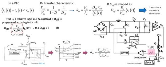
This circuit is intrinsically stable considering the inductor presence in the current loop.
Application for the vienna rectifier
Considering the simplicity of this approach, it would be interesting to apply a similar technique to the Vienna rectifier. This is what the authors have shown (see source 2)) but without proposing an application circuit. I looked into this possibility via LTspice and SIMPLIS. The first schematic using SPICE as a simulator is proposed in Figure 2. Starting from the left, the inductor currents are rectified then scaled by the sense resistances Ri. The resulting voltages go through an integrating active filter featuring a single pole. The filtered signal is then applied to the inverting pin of the current sense comparator.
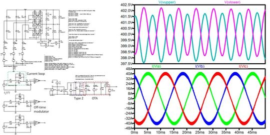
The non-inverting pin of this comparator receives the sawtooth (30 kHz in this example) whose slope is adjusted by the timing capacitor charging current (Ct in the figure). This current depends on the error voltage which sets the off-time value in relationship with the output power. The error voltage is elaborated with a transconductance operational amplifier (OTA), compensated as a type 2. This filter involves a pole at the origin and a pole-zero pair for boosting the phase at the selected crossover frequency.
In this example, the three-level converter delivers 10 kW to an 800-V total bus voltage, supplied from a 120-VL-N voltage. The input current waveforms are very clean with a low total harmonic distortion (THD < 5%). The output voltages are also well regulated at 400 V each when considering equal current consumptions from the output loads. The authors have described a way to ensure output voltages balancing but I did not explore the option in this simple implementation.
Stabilizing the loop
The cornerstone of any small-signal analysis starts with the control-to-output transfer function. This complex expression describes the relationship between a stimulus and a response: if you apply a sinusoidal signal to the control input of your power converter, how does this stimulus propagate through the various nodes and meshes to create a response that is observed at the converter output? You can obtain this ac response either via an analytical analysis, a simulation or a hardware experiment. The analytical analysis is complicated for a three-phase converter and requires adequate solvers to plot the ac response you need. Building the converter is a possible option – sometimes the only one – but extracting the response from a live high-power system is always a perilous exercise and requires adequate equipment. In the end, a piece-wise linear (PWL) simulator represents a good alternative to obtain the Bode plot of your choice. There are several engines on the market, and I personally used SIMPLIS for this purpose.
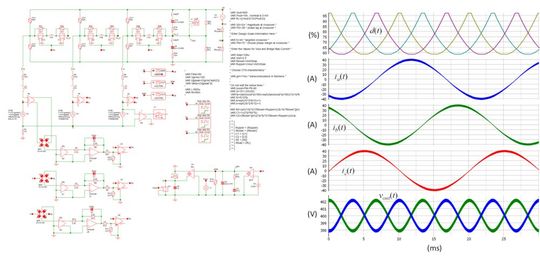
Figure 3 shows how this adopted schematic diagram is close to the one I simulated with LTspice. One difference though, SIMPLIS does not provide analog behavioral models (ABM) and requires an electronic circuit for building mathematical functions. In my circuit, I could not use the absolute value SPICE function ABS to rectify the input currents. Rather, I resorted to a full-bridge rectifier, made of perfect diodes with a negligible forward drop. The rest of the architecture is identical to the LTspice circuit. One thing worth noting here is the ability of SIMPLIS to extract the ac response while the three ac sources are alive. This is a major difference with average models which lets you extract the response of the modeled PFC but with a dc bias in lieu of the ac source. In our Vienna case, the converter operates from the three-phase network and delivers power to the selected load. SIMPLIS determines the periodic operating point or POP and ac-sweeps the circuit to deliver the control-to-output transfer function of the power stage. The POP results are essential to confirm that the correct steady state is obtained. This is illustrated by the waveforms shown on the right side of Figure 3. The switching frequency is 30 kHz and the input voltage line-neutral is 120 V rms.
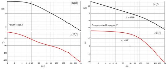
After a few minutes, the ac response is plotted and appears in Figure 4. The power stage response shows up on the left side. From this graph, we can extract the magnitude and phase at the selected crossover frequency, 40 Hz in this example. These data are fed to the right-side macro of Figure 3 which automates component calculations for a type 2 compensator. The compensated gain curve from Figure 4 confirms the correct crossover frequency with a comfortable phase margin of 60°. These data will now be transferred to the LTspice simulation for the transient response test.
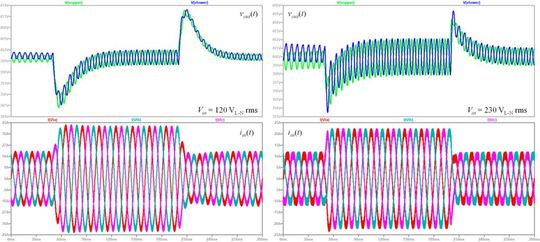
In this test, the output power is stepped from 5 to 10 kW at two input voltage extremes. As you can observe in Figure 5, the voltage drop is well controlled in both cases (≈10-V deviation at low line), with a good recovery and absence of oscillations. With symmetrical loads, the output voltage rails keep well in line.
The LTspice files can be freely downloaded 5).
Conclusion
The control of the Vienna rectifier via variable off-time generator has been described in 2005. In this short article, I have shown how to simulate a simple version of the converter when operated in this mode. The loop is stabilized with the help of SIMPLIS which can extract the ac response while the switching converter is supplied from the three-phase network. Transient response plots confirm the stability of the compensated rectifier.
References
1) C. Basso, Average Models are Versatile Design Companions, PCIM News Platform, July 2026
2) J. Miniböck, J. Kolar, F. Stögerer, Novel Concept for Mains Voltage Proportional Input Current Shaping of a VIENNA Rectifier Eliminating Controller Multipliers, APEC, February 2005
3) J. Gegner, C. Lee,Linear peak current mode control: a simple active power factor correction control technique for continuous conduction mode, PESC, June 1996
4) S. Ben-Yaakov, I. Zeltzer, PWM converters with resistive input, IEEE Transactions on Power Electronic, Vol. 45, no. 3, June 1998
5) C. Basso, Summer 2025 LTspice files collection, released in July 2025 from the author webpage
(ID:50997686)