


:quality(80)/p7i.vogel.de/wcms/7f/4b/7f4b97757cea82c0675209630577dc22/0133974130v2.jpeg "Vox Power’s EIRE600 delivers up to 600 W in a compact 5 × 3-inch package, with forced-air or conduction cooling options for industrial and medical equipment. (Source: Vox Power)")
:quality(80)/p7i.vogel.de/wcms/55/97/5597c3436e3bc92ee7ba23b6f9d289e9/0134032539v2.jpeg "Littelfuse’s TP7.0SMD-XC automotive TVS diode series uses foldback technology to provide low clamping voltage for protecting sensitive vehicle electronics. (Bild: Littelfuse)")
:quality(80)/p7i.vogel.de/wcms/51/f8/51f84448e666230bb11a02566abd1177/0133958187v3.jpeg "Microchip’s radiation-tolerant GaN point-of-load converter supplies up to 20 A for space-based processors, FPGAs, microcontrollers and ASICs. (Source: Microchip)")
:quality(80)/p7i.vogel.de/wcms/0a/7c/0a7c08f368ae1d91f758dd18d2a32e88/0133978423v2.jpeg "EPFL researchers have demonstrated a GaN transistor that withstands nearly 4 kV, using an intrinsic polarization superjunction design to distribute electric fields more evenly. (Source: EPFL)")
:quality(80)/p7i.vogel.de/wcms/5b/94/5b94232ca4183d6fcc2dccc7394d7544/0134041114v4.jpeg "Siemens and NVIDIA are testing AI applications at Siemens’ Erlangen electronics factory, using digital twins to support production planning and prepare inspection systems before physical prototypes are available. (Bild: Siemens)")
:quality(80)/p7i.vogel.de/wcms/b4/1f/b41f2731a07b608e60eca3663e280301/0133980549v2.jpeg "Multi-year agreement with Wolfspeed supports Infineon’s conversion from 150-millimeter to 200-millimeter silicon carbide (SiC) manufacturing (Source: © Ada - stock.adobe.com)")
:quality(80)/p7i.vogel.de/wcms/e3/0a/e30a8813bcf44b16f0dceb63a0747d29/0133984094v2.jpeg "The semiconductor is only one part of the design. Higher voltage, frequency and power density also increase the demands on electronic packaging materials such as die attach, substrates, top-side interconnects and module attach. (Source: Generated by AI)")
:quality(80)/p7i.vogel.de/wcms/5d/fb/5dfba5e5f38daf2b8597b05656af29c0/0133956337v2.jpeg "Wolfspeed has received a conditional commitment for a loan of up to $1.5 billion from the U.S. Department of War to support its domestic wide-bandgap semiconductor supply chain. (Source: © AspctStyle - stock.adobe.com)")
:quality(80)/p7i.vogel.de/wcms/bf/b6/bfb6ac295759be32d567df9849b6767e/0134094495v2.jpeg "Fraunhofer ISE reports that 25 Ah pouch cells with silicon-rich anodes retained more than 83% of their initial capacity after 1,000 cycles when tested under 1,000 kPa axial pressure. (Bild: Fraunhofer ISE)")
:quality(80)/p7i.vogel.de/wcms/16/dc/16dca55e6ef80e6b5da68bc628da2dcc/0133844782v2.jpeg "This article explains virtual power plants in modern renewable-heavy grids. (Source: © M@rketVisualsStudio - stock.adobe.com)")
:quality(80)/p7i.vogel.de/wcms/e8/33/e8330aae4bea3578b98ec2c1403d367a/0133980001v2.jpeg "IRENA’s 2026 World Energy Transition Outlook identifies faster electrification powered by renewables as central to meeting future global energy needs. (Source: Irena)")
:quality(80)/p7i.vogel.de/wcms/6c/b4/6cb405f47d25035e256ae90fe3a66ee6/0134032112v2.jpeg "Sungrow’s PowerTitan 3.0 energy storage platform uses onsemi EliteSiC hybrid power modules, with the companies reporting peak inverter efficiency above 99.3%. (Bild: onsemi)")
:quality(80)/p7i.vogel.de/wcms/7b/76/7b76005554b556df2a7a3794bdf69d44/0132365246v2.jpeg "Hioki’s ST5680A DC Hipot Tester combines CE/UKCA/CSA compliance, an integrated capacitance‑based contact check and time‑series waveform recording (voltage, leakage current, insulation resistance) to standardize hipot and insulation testing across EV cell, module and pack production lines. (Source: Hioki)")
:quality(80)/p7i.vogel.de/wcms/af/7f/af7f7b0fb7f29219fc991b1130f65477/0132241333v2.jpeg "Comprehensive laboratory testing regimens—combining thermal cycling, high‑current stress, EMC, and accelerated lifetime tests—are essential to validate advanced power designs and ensure reliability in real‑world applications. (Source: PRBX)")
:quality(80)/p7i.vogel.de/wcms/16/3d/163df69363f8125315a9826e13ea4b05/0131927425v2.jpeg "Solution will maximize data center and AI factory profitability while delivering engineering-grade insights to design and operations for more efficient, sustainable, and resilient infrastructure. (Source: Cadence)")
:quality(80)/p7i.vogel.de/wcms/85/b7/85b7e90733a2bd8f21515d8f7137f2fc/0131917677v2.jpeg "Renesas acquires Pictorus to integrate its embedded application software platform with Renesas’ MCU and MPU portfolio, helping developers shorten time‑to‑market and simplify system integration. (Source: © lucadp - stock.adobe.com)")
:quality(80)/p7i.vogel.de/wcms/f8/34/f834240d434a0c265a2ccafe614c8cd7/0134032109v4.jpeg "Hard- and soft-switching techniques shape voltage and current during device transitions, influencing switching losses, EMI and thermal performance in power converters. (Bild: © Mrthullab - stock.adobe.com)")
:quality(80)/p7i.vogel.de/wcms/27/07/2707280c807689b437baed3660257404/0133626052v2.jpeg "The quantum behavior of electrons shapes semiconductor devices—and the power converters that deliver electricity to modern computing systems. (Source: © Celt Studio - stock.adobe.com)")
BASIC KNOWLEDGE Grid-forming inverters: How they work and why grids need them
Related Vendors
:fill(fff,0)/p7i.vogel.de/companies/68/2c/682c3e2e9a195/logotype-rvb.jpeg "logotype-rvb (MERSEN France)")
:fill(fff,0)/p7i.vogel.de/companies/66/8b/668becd1c07eb/dowa-logo-word--1-.jpeg "dowa-logo-word--1- (DOWA)")
The world is transitioning from the conventional grid to the renewable-dominated one, backed by solar, wind, and batteries. The problem with the renewable-backed grid is the lack of stability. Instead of synchronous generators, it uses inverter-based resources (IBR) to facilitate stable operation. However, when a disturbance hits, the inverter system has very little to hold it together. Times have changed as newer types, such as grid-forming inverters (GFMs), start supporting the grid.

Grid-forming inverters are defined by the software, rather than the hardware. The same way software-defined power electronics (SDPE) defines software-defined vehicles (SDVs).
What is a grid-forming inverter?
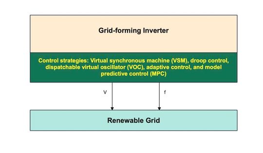
A grid-forming inverter is a power electronics converter that sets its own voltage and frequency instead of synchronizing with the existing grid. In short, grid-forming inverters perform the standard operation of converting DC from the renewable source (battery, solar, or wind) into AC for the grid, but are independent of the grid voltage and frequency. Whenever frequency and voltage fluctuate, grid-forming inverters respond instantly by holding their reference voltage steady and supplying the required current to keep the grid stable and prevent outages.
Why grid-forming inverters?
The conventional grid is backed by synchronous generators, whose physics combats any rate-of-change-of-frequency (RoCoF) events. Whenever the frequency, whether 50 Hz or 60 Hz, shifts, the synchronous generators don’t stop. They provide inertia as a by-product of their spinning mass to prevent generators from stopping. You can learn about the missing physics of renewables here.
When grids become renewable, IBRs have no physics to generate inertia and prevent grid downtime because they act when they first sense a faulty frequency or voltage. The grid-forming inverter automatically holds its own voltage and frequency by instantly supplying the power the grid needs. This means that grid-forming inverters don’t wait to detect a fault; they automatically have the response ready. No blackout occurs.
There is no specific grid-forming inverter symbol; instead, it is represented as a “GFM” block in the diagram. Some sources can also use the inverter symbol ~ to depict grid-forming inverters.
There are several control strategies engineers use in grid-forming inverters. They add more to the GFM bill of materials (BOM files).
Droop control: The word “droop” means to bend or hang downwards because of a lack of strength. Similarly, droop control works by allowing all power sources to lower their frequencies or voltages up to a permissible limit. In droop control-based GFM inverters, multiple power sources are connected in parallel. Based on their power ratings, the load is divided among them proportionally.
Each of them is assigned a droop value. This means that they are only allowed to deviate from the grid frequency and voltage in accordance with the assigned values. Droop control is an established strategy in GFM inverters; however, it reacts to the event only in proportion to the values. So in a weak grid, sudden swings can push beyond safe limits until the droop settles them.
Virtual synchronous machine (VSM): When grid frequency or voltage alters, synchronous generators, by their physics, try to remain in the same state of motion. They provide inertia to prevent alteration of grid frequency and voltage. A virtual synchronous machine functions like a synchronous generator by providing virtual inertia, known as “synthetic inertia”, to stabilize the grid.
Simply put, the VSM control strategy pushes extra power when the grid frequency declines and draws when the grid frequency increases. VSM follows software algorithms, commonly the swing equation, to simulate the behavior of a synchronous generator connected to distributed power sources.
It simulates their physical and electrical characteristics, including rotating mass, ability to self-synchronize with the grid, high impedance, and large inertia. VSM control strategy is suitable for grids transitioning from conventional systems to renewable-heavy implementation. It holds backend compatibility with legacy grid infrastructure.
Virtual oscillator control: Instead of copying a synchronous generator, the virtual oscillator control (VOC) method mimics a self-sustaining nonlinear oscillator. In simple words, VOC GFM inverters are based on natural oscillator behavior. Voltage and frequency are regulated in accordance with internal states.
All connected power sources hold the grid’s nominal voltage and frequency. When a RoCoF event occurs, they snap back to the same nominal values. Each source is independent of the others, reducing the reliance on communication. However, coordinating a large number of sources can be problematic, which is why VOC performs the best in islands and microgrids.
Adaptive control: GFM inverters using an adaptive control strategy can dynamically adjust inverter parameters to combat faulty grid events. Adaptive algorithms need to continuously record values of grid voltage, frequency, power, current, and other important parameters to optimize inverter performance. It is suitable for islands and microgrids because data acquisition adds complexity and cost.
Benefits of grid-forming inverters
At present, grid-following inverters, a predecessor of grid-forming inverters, dominate the renewable grid. Grid-forming inverters have shown excellent performance in practical deployments. The U.S Department of Energy funded an initiative known as Universal Interoperability for Grid-forming Inverters (UNIFI) to promote grid-forming inverters.
Benefits of grid-forming inverters include the following.
- 1. Regulate voltage: Grid-forming inverters provide stable output AC voltage for proper grid functioning.
- 2. Synthetic inertia: Grid-forming inverters provide synthetic inertia to resist frequency fluctuations in RoCoF events.
- 3. Autonomous operation: Grid-forming inverters can automatically regulate voltage and frequency without taking reference from the actual grid.
- 4. Instant response: Grid-forming inverters react as soon as grid parameters deviate.
- 5. Smooth operation: Grid-forming inverters don’t embed grid parameters in a feedback loop to generate their output. Such interactions can sometimes generate oscillations.
- 6. Black-start capabilities: If grid-forming inverters are deployed with energy storage solutions, they can restore grid operation from total blackouts and outages.
- 7. Interoperability: Grid-forming inverters are compatible with legacy grids. They enable integration of distributed energy resources (DERs), including PVs, batteries, and wind turbines.
- 8. Seamless islanding: Grid-forming inverters can transition smoothly, without causing surges, between grid-connected and islanded operations.
- 9. Facilitating renewable penetration: Grid-forming inverters enable the grid to run on more IBRs, about 60-70%.
- 10. Fewer curtailments: By stabilizing the grid, grid-forming inverters reduce the operator’s need to switch off clean energy.
Challenges for grid-forming inverters
In the faulty condition, GFM inverters have to supply whatever current, roughly 1.2-1.5 times the normal, to stabilize grid voltage. Switches must be able to handle such current surges. In general, IBRs in renewable-grid use IGBTs for their low cost and optimal performance.
Grid-forming inverters call for silicon carbide (SiC) MOSFETs for their fast switching speed, power handling capability, and heat management. SiC MOSFETs and other components increase the overall cost of GFMs.
The only downside of grid-forming inverters is that they’re new. However, with better features and outcomes, they cost more. Due to the performance benefits, the industry is commissioning more projects and inviting investment to promote GFM deployment in the renewable grid infrastructure.
References
https://in.mathworks.com/discovery/grid-forming-inverter.html
https://iea-isgan.org/grid-forming-inverter/
https://ieeexplore.ieee.org/document/6652456
https://in.mathworks.com/discovery/droop-control.html
https://ieeexplore.ieee.org/document/8662197
https://www.sciencedirect.com/science/article/pii/S2352484723002810
https://www.mdpi.com/2079-9292/15/5/1115
https://unificonsortium.org/#:~:text=The%20Universal%20Interoperability%20for%20Grid%2DForming,effort%20to%20advance%20grid%2Dforming%20(GFM
https://spectrum.ieee.org/electric-inverter
(ID:50946586)
:quality(80)/p7i.vogel.de/wcms/16/dc/16dca55e6ef80e6b5da68bc628da2dcc/0133844782v2.jpeg "This article explains virtual power plants in modern renewable-heavy grids. (Source: © M@rketVisualsStudio - stock.adobe.com)")
:quality(80)/p7i.vogel.de/wcms/c2/c5/c2c511e7ac135d380af0e8a85decfb7c/0131575680v2.jpeg "This article discusses the problem with renewable grids and how FACTS devices can help. (Source: © Endang - stock.adobe.com)")