


:quality(80)/p7i.vogel.de/wcms/7f/4b/7f4b97757cea82c0675209630577dc22/0133974130v2.jpeg "Vox Power’s EIRE600 delivers up to 600 W in a compact 5 × 3-inch package, with forced-air or conduction cooling options for industrial and medical equipment. (Source: Vox Power)")
:quality(80)/p7i.vogel.de/wcms/55/97/5597c3436e3bc92ee7ba23b6f9d289e9/0134032539v2.jpeg "Littelfuse’s TP7.0SMD-XC automotive TVS diode series uses foldback technology to provide low clamping voltage for protecting sensitive vehicle electronics. (Bild: Littelfuse)")
:quality(80)/p7i.vogel.de/wcms/51/f8/51f84448e666230bb11a02566abd1177/0133958187v3.jpeg "Microchip’s radiation-tolerant GaN point-of-load converter supplies up to 20 A for space-based processors, FPGAs, microcontrollers and ASICs. (Source: Microchip)")
:quality(80)/p7i.vogel.de/wcms/0a/7c/0a7c08f368ae1d91f758dd18d2a32e88/0133978423v2.jpeg "EPFL researchers have demonstrated a GaN transistor that withstands nearly 4 kV, using an intrinsic polarization superjunction design to distribute electric fields more evenly. (Source: EPFL)")
:quality(80)/p7i.vogel.de/wcms/5b/94/5b94232ca4183d6fcc2dccc7394d7544/0134041114v4.jpeg "Siemens and NVIDIA are testing AI applications at Siemens’ Erlangen electronics factory, using digital twins to support production planning and prepare inspection systems before physical prototypes are available. (Bild: Siemens)")
:quality(80)/p7i.vogel.de/wcms/b4/1f/b41f2731a07b608e60eca3663e280301/0133980549v2.jpeg "Multi-year agreement with Wolfspeed supports Infineon’s conversion from 150-millimeter to 200-millimeter silicon carbide (SiC) manufacturing (Source: © Ada - stock.adobe.com)")
:quality(80)/p7i.vogel.de/wcms/e3/0a/e30a8813bcf44b16f0dceb63a0747d29/0133984094v2.jpeg "The semiconductor is only one part of the design. Higher voltage, frequency and power density also increase the demands on electronic packaging materials such as die attach, substrates, top-side interconnects and module attach. (Source: Generated by AI)")
:quality(80)/p7i.vogel.de/wcms/5d/fb/5dfba5e5f38daf2b8597b05656af29c0/0133956337v2.jpeg "Wolfspeed has received a conditional commitment for a loan of up to $1.5 billion from the U.S. Department of War to support its domestic wide-bandgap semiconductor supply chain. (Source: © AspctStyle - stock.adobe.com)")
:quality(80)/p7i.vogel.de/wcms/bf/b6/bfb6ac295759be32d567df9849b6767e/0134094495v2.jpeg "Fraunhofer ISE reports that 25 Ah pouch cells with silicon-rich anodes retained more than 83% of their initial capacity after 1,000 cycles when tested under 1,000 kPa axial pressure. (Bild: Fraunhofer ISE)")
:quality(80)/p7i.vogel.de/wcms/16/dc/16dca55e6ef80e6b5da68bc628da2dcc/0133844782v2.jpeg "This article explains virtual power plants in modern renewable-heavy grids. (Source: © M@rketVisualsStudio - stock.adobe.com)")
:quality(80)/p7i.vogel.de/wcms/e8/33/e8330aae4bea3578b98ec2c1403d367a/0133980001v2.jpeg "IRENA’s 2026 World Energy Transition Outlook identifies faster electrification powered by renewables as central to meeting future global energy needs. (Source: Irena)")
:quality(80)/p7i.vogel.de/wcms/6c/b4/6cb405f47d25035e256ae90fe3a66ee6/0134032112v2.jpeg "Sungrow’s PowerTitan 3.0 energy storage platform uses onsemi EliteSiC hybrid power modules, with the companies reporting peak inverter efficiency above 99.3%. (Bild: onsemi)")
:quality(80)/p7i.vogel.de/wcms/7b/76/7b76005554b556df2a7a3794bdf69d44/0132365246v2.jpeg "Hioki’s ST5680A DC Hipot Tester combines CE/UKCA/CSA compliance, an integrated capacitance‑based contact check and time‑series waveform recording (voltage, leakage current, insulation resistance) to standardize hipot and insulation testing across EV cell, module and pack production lines. (Source: Hioki)")
:quality(80)/p7i.vogel.de/wcms/af/7f/af7f7b0fb7f29219fc991b1130f65477/0132241333v2.jpeg "Comprehensive laboratory testing regimens—combining thermal cycling, high‑current stress, EMC, and accelerated lifetime tests—are essential to validate advanced power designs and ensure reliability in real‑world applications. (Source: PRBX)")
:quality(80)/p7i.vogel.de/wcms/16/3d/163df69363f8125315a9826e13ea4b05/0131927425v2.jpeg "Solution will maximize data center and AI factory profitability while delivering engineering-grade insights to design and operations for more efficient, sustainable, and resilient infrastructure. (Source: Cadence)")
:quality(80)/p7i.vogel.de/wcms/85/b7/85b7e90733a2bd8f21515d8f7137f2fc/0131917677v2.jpeg "Renesas acquires Pictorus to integrate its embedded application software platform with Renesas’ MCU and MPU portfolio, helping developers shorten time‑to‑market and simplify system integration. (Source: © lucadp - stock.adobe.com)")
:quality(80)/p7i.vogel.de/wcms/f8/34/f834240d434a0c265a2ccafe614c8cd7/0134032109v4.jpeg "Hard- and soft-switching techniques shape voltage and current during device transitions, influencing switching losses, EMI and thermal performance in power converters. (Bild: © Mrthullab - stock.adobe.com)")
:quality(80)/p7i.vogel.de/wcms/27/07/2707280c807689b437baed3660257404/0133626052v2.jpeg "The quantum behavior of electrons shapes semiconductor devices—and the power converters that deliver electricity to modern computing systems. (Source: © Celt Studio - stock.adobe.com)")
POWER SYSTEMS FACTS devices and the missing physics of renewable-heavy grids
Related Vendors
:fill(fff,0)/p7i.vogel.de/companies/5f/71/5f71d5f92a5f6/2000px-rogers-corporation-logo-svg.png "2000px-Rogers_Corporation_Logo.svg.png (rogers germany)")
:fill(fff,0)/p7i.vogel.de/companies/68/2c/682c3e2e9a195/logotype-rvb.jpeg "logotype-rvb (MERSEN France)")
:fill(fff,0)/p7i.vogel.de/companies/66/8b/668becd1c07eb/dowa-logo-word--1-.jpeg "dowa-logo-word--1- (DOWA)")
Flexible AC transmission systems (FACTS) devices handle peak power management when load demand spikes or transients occur due to weather. The problem with “peak hours" is that they don’t stay continuous, but exist for a small duration at specific, predictable times. FACTS devices come to the rescue where laying an additional transmission line or adding a substation to handle peak load is costly, impractical, and troublesome. The devices were commercialised around the 1980s, but failed to reach large-scale adoption.
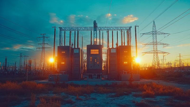
FACTS devices saw limited adoption despite proven performance due to technical integration challenges and economic factors. Unlike transformers, FACTS devices are not available as plug-and-play solutions for the grid. They are custom-built, making the development and circuit design cycles long.
Instead of deploying FACTS devices, transmission system operators (TSOs) in various countries, including the US, UK, and Germany, prioritised building new transmission lines. Adopting renewable-backed power generation technologies accelerated transmission line projects.
TSO built new 400 kV lines instead of developing and deploying FACTS devices. Despite the promise, FACTS devices were less deployed. In the 2010s, transmission line projects got slow approvals from governments and regulatory bodies. That’s when renewables started to create problems in response to transient events and weather conditions.
Where does the renewable grid lack?
Power generation facilities on the grid use large synchronous generators to output AC electricity at the final stage. AC power relies on a stable frequency, such as 50 Hz or 60 Hz, for operation. Every machine on the grid is synchronised to the same frequency, which must stay stable. The rotor of the generator spins at a speed proportional to grid frequency.
When electricity demand equals generation, the grid frequency remains constant. All connected units remain balanced. Misalignment of electricity demand and generation alters rotor speed. If electricity demand increases, rotors slow down to release kinetic energy. The slowing rotor reduces grid frequency. Whereas decreasing electricity demand speeds up rotors to absorb kinetic energy. The grid frequency starts to increase.
According to Newton’s first law of motion, a moving/spinning object “naturally” resists a change of state of motion. Simply put, a speeding object resists slowing down, and a resting object resists moving. Due to inertia, rotors resist the change in motion, whether they are slowing down or accelerating. Operators get extra seconds to react before the frequency moves too far.
In practical situations, not all rotors slow down or speed up together. Rotors present in the vicinity of the change react first, followed by other distant rotors. Timing mismatch makes them swing against each other, similar to two pendulums searching for balance. Synchronous machines can physically damp these swings through damper windings, torque, and system stabilisers.
Renewable grids incorporate a small number of synchronous machines. Inverter-based resources (IBR) handle operations through digital control systems. Simply put, software controls the entire inverter system in renewable grids. The inverter code may dampen oscillations or contribute to inertia-like effects. However, synchronous machines are more effective because of physics.
The debate of synchronous machines and inverter-based resources is based on a comparison between physics-driven actions and software performance. Due to the absence of inertia and damping mechanisms, renewable grids with IBRs face a higher rate of change of frequency events (RoCoF). RoCoF events can hinder power supply and cause serious blackouts.
In April 2025, the Iberian Peninsula, the landmass in Southwestern Europe, faced a blackout due to two dangerous voltage oscillations. Renewable infrastructure comprised 78% of the grid, with solar power being 60%. A cascade of generators was disconnected. The peninsula region was desynchronized, leading to a 10-hour (or more) blackout.
Weather crisis for the renewable-backed grid
Natural calamities and extreme weather affect electricity generation and supply, whether the power generation is renewable or not. But synchronous machines can tackle transient responses better than renewable energy sources, which face significant challenges even in normal weather conditions. Cloudy or rainy days can affect solar cell power generation. Low-speed winds can hinder electricity generation in wind farms.
In 2019, a lightning strike near Cambridge triggered a fault on a 400 kV transmission line, which was resolved in milliseconds. Hornsea One offshore wind farm could not fight voltage transients. The frequency dropped from 50 Hz to 48.8 Hz. The wind farm was deloaded from 799 MW to 62 MW. A post-investigation report suggested that the wind farm accepted that the grid code requirements were not met, and the voltage control system wasn’t efficient enough to dampen swings.
Freezing temperatures can cause critical damage to grid infrastructure. Snow from such temperatures puts a load (weight) on equipment such as windmill blades, solar panels, and substation switchgear. The 2021 winter storm in Texas, US, is a classic example of 20 W load shedding. Nearly 4.5 million people lost power for 4 days (Approximately). Solar infrastructure capacity at 750 MW fell 12%.
What does the FACTS Toolkit do?
There are three types of power. Real power (P) does the “visible work” in electrical systems. Spins the motor, lights the bulb, heats the element, keeps the processor running, and performs various other functions. Measurable in Watts. Apparent power (S) is the total power flowing in the line. Measurable in volt-amperes. Apparent power doesn’t reach the end point for use.
Apparent power is the vector sum of real power (P) and reactive power (Q). Reactive power does all the “invisible work” with magnetic and electric fields. Measurable in volt-ampere reactive. FACTS devices use power electronic devices to control reactive power in a high-voltage AC (HVAC) transmission line.
FACTS devices keep the voltage stable and ensure the grid delivers more real power. All FACTS devices are known as compensators because they compensate for reactive power imbalances. There are three main classes of FACTS devices:
Shunt compensation devices: Shunt compensation devices, such as shunt capacitors and reactors (inductors), are connected in parallel with the power system or near industrial loads. These devices can either inject or absorb reactive power at a single point to stabilise the voltage. Static VAR compensators (SVC) use thyristor-controlled reactors (TCR) or capacitors to regulate voltage, correct power factor, and stabilize the electrical grid.
The new generation of shunt compensators uses semiconductor switches, such as MOSFETS, JFETs, and IGBTs. Static synchronous compensator (STATCOM) uses IGBT or SiC MOSFETs in series with a reactor to form a voltage-source converter to provide reactive power service and support voltage control. The main operating principle is to vary the voltage of power electronic devices to control reactive power flow. Renewable grids prefer STATCOM with battery or supercapacitor energy storage.
Series compensation devices: Series compensation devices insert controllable impedance into the transmission line to control power flow and reroute oscillations. A series capacitor is installed in line with the high-voltage transmission line to neutralise inductive reactance, enhance voltage stability, and optimise power flow.
The thyristor-controlled series capacitor (TCSC) switches a thyristor-controlled reactor (TCR), as discussed in SVC, to control line reactance and damp sub-synchronous resonance. The static synchronous series compensator (SSSC) is a series compensator that uses a voltage-source converter (Described in STATCOM). SSSC is connected to the secondary winding of a transformer, which is connected in series with the power system.
Unified power flow controller: Unified power flow controller (UPFC) combines a STATCOM (shunt compensator) with an SSSC (series compensator) using a common DC link. UPFC can effectively control reactive and active power flow in high-voltage transmission lines. It’s faster and more flexible than all other FACTS devices. UPFCs are used in high-congestion points, making them expensive to deploy.
Sudden rise of FACTS devices
Coal decommissioning and renewable-backed systems have facilitated the FACTS device market. Since 2020, FACTS devices market reports have been circulating online. Pre-2015 FACTS market data is scarce due to low installation volumes. Transparency Market Research forecasts USD2.28 billion market for FACTS devices in 2031.
Various reports suggest billion-dollar investments were directed towards FACTS devices in 2023. STATCOM occupies most deployed FACTS devices. Some sources estimate Germany needs 70 STATCOMs in a decade to ensure grid stability. Siemens Energy has built a supercapacitor-backed “E-STATCOM” at Mehrum, Lower Saxony, Germany. Siemens shipped the 100th STATCOM from the SVC Plus series in 2019. The numbers show how narrow, customised, and expensive the FACTS device category is.
References
- https://www.sciencedirect.com/science/article/pii/S2352484724002919
- https://www.bakerinstitute.org/research/iberian-peninsula-blackout-causes-consequences-and-challenges-ahead
- https://www.solarpowerportal.co.uk/solar-technology/blackout-investigation-what-went-wrong-at-hornsea-one-and-little-barford
- https://www.spglobal.com/energy/en/news-research/latest-news/electric-power/022421-ercot-lost-almost-half-of-generation-capacity-in-storm-causing-20-gw-load-shed
- https://www.siemens-energy.com/global/en/home/stories/grid-stability-first-e-statcom.html
(ID:50859028)
:quality(80)/p7i.vogel.de/wcms/24/f7/24f7b223072f64176ddf7b0e80b3c04a/0132153842v2.jpeg "Rapid growth in wind and solar has created periods of electricity abundance that ageing transmission grids often cannot absorb, forcing curtailment and underscoring the urgent need for grid upgrades, storage and smarter distribution strategies. (Source: © Giggles - stock.adobe.com)")
:quality(80)/p7i.vogel.de/wcms/cc/f0/ccf0b07809eaa14635374ad332fd7ea3/0129431466v2.jpeg "Power semiconductors enable fast, precise control in increasingly decentralized and renewable-driven power grids. (Source: © Anusa - stock.adobe.com)")