


















ELECTROMAGNETIC POWER Fundamentals of magnetics in power electronics
Related Vendors


The basic building blocks of switching power converters are magnetic components. Semiconductor devices and control circuits control the electrical energy. Inductors store energy and filter currents, while transformers change voltage levels and provide electrical isolation. Coupled inductors, such as the flyback magnetic component discussed later, combine energy storage with isolation.

They behave according to electromagnetic laws that directly affect converter efficiency, power density and thermal performance. As switching frequencies increase and designers try to make power conversion systems smaller, it is becoming increasingly important to understand these principles.
In practice, magnetic components are non-linear, lossy, and limited by the core materials and winding structures, unlike ideal circuit elements. Their design is not always de-coupled from the converter. This paper presents basic ideas about magnetics in power electronics including magnetic flux, permeability, magnetic circuits, saturation and main loss mechanisms.
Power by Maurizio
About the author

Maurizio Di Paolo Emilio is a physicist, engineer, and technical author with a passion for technology and innovation. Curious by nature, he explores how technology works, how it evolves, and where it is heading.
From electrical current to magnetic flux
Magnetic components operate on the relationship between electric current and magnetic fields. When electric current flows through a conductor, it generates a magnetic field around it. When a coil is wound around a magnetic core, the multiple turns of the coil combine to produce a magnetic field that can be concentrated within the core material.
Two quantities are especially important: magnetic field strength, (H), measured in amperes per meter; and magnetic flux density, (B), measured in tesla.
Magnetic flux density describes the magnetic field in terms of flux per unit area perpendicular to the field, while magnetic flux, (Φ), measured in webers (Wb, with 1 T = 1 Wb/m2), represents the total magnetic flux passing through a given surface
For a uniform flux distribution across a core cross-sectional area (Ac), the relationship is:
Φ = BAc
The magnetic properties of the core determine how flux density responds to an applied magnetic field. For a linear magnetic material:
B = μH
where 𝜇 is the magnetic permeability.
A material with high permeability can support a relatively large flux density for a given magnetic field strength. This property makes magnetic cores useful for concentrating flux and obtaining practical inductance values with a limited number of winding turns.
However, the relationship between (B) and (H) is not always linear. Real magnetic materials exhibit saturation and hysteresis, which must be considered when designing power converters.
The laws behind magnetic components
Two electromagnetic laws explain the interaction between electrical and magnetic quantities.
Faraday's law describes how a changing magnetic flux induces voltage in a winding. For a winding with (N) turns linked by the same flux:
With approximately uniform flux density across the core:
These equations show that the applied winding voltage determines the rate at which magnetic flux changes, assuming the winding voltage is approximately equal to the induced voltage and resistive voltage drops are negligible.
Integrating the second equation gives the flux density as a function of the applied voltage:
A rectangular voltage 𝑉 applied for a time 𝑡𝑜𝑛 therefore produces a flux-density change
which depends on the volt-seconds applied and not on the load current. It decreases with a larger number of turns or a larger core area. For example, a symmetric square wave of amplitude ±𝑉 at frequency 𝑓 gives a peak flux density
In switching converters, this relationship is particularly important because the voltage waveform applied to a winding determines its flux-density excursion. Excessive applied volt-seconds can drive a magnetic core toward saturation. In steady state the average voltage across a winding must be zero (volt-second balance): any DC component of the applied voltage makes 𝐵 drift until the core saturates or resistive drops limit it.
Ampere's law provides the complementary relationship between winding current and magnetic field strength.
For a simplified ungapped magnetic core with uniform magnetic field strength and mean magnetic path length (lc):
The product (Ni) is known as magnetomotive force (MMF). It represents the excitation responsible for establishing magnetic flux in the magnetic circuit.
For a magnetic core containing an air gap, the magnetomotive force is distributed across both the core and the gap:
where (Hc) and (Hg) are the magnetic field strengths in the core and air gap, respectively, and (g) is the air-gap length. This expression assumes a simplified magnetic path with negligible leakage flux and approximately uniform magnetic fields in each region.
Together, Faraday's and Ampere's laws connect the electrical behavior of a winding to the magnetic properties of its core.
Understanding magnetic circuits
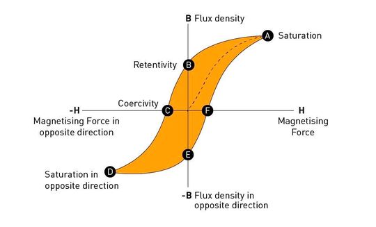
Magnetic structures can be analyzed using an approach similar to conventional electrical circuit analysis. In an electrical circuit, voltage drives current through resistance. In a magnetic circuit, magnetomotive force establishes magnetic flux through reluctance.
Reluctance describes the opposition of a magnetic path to the establishment of flux. For a uniform magnetic core:
where lc is the mean magnetic path length in the core, 𝜇 is the core permeability, and (Ac) is the cross-sectional area.
For an air gap of length (g), assuming a uniform cross-sectional area and neglecting fringing, the corresponding reluctance is:
where 𝜇0 is the permeability of free space.
The resulting relationship is:
where ℱ represents magnetomotive force and ℛ is the reluctance of the magnetic path.
This analogy provides a useful way to understand how core geometry, material properties, and air gaps influence magnetic behavior.
Since the flux linkage of the winding is 𝜆=𝑁𝛷 and 𝑁𝑖=ℛ𝛷, the inductance is:
For the series core-and-gap path
The energy stored in the magnetic field is
Equivalently, the energy stored per unit volume is
which reduces to
in a linear material. Because approximately the same flux density 𝐵 crosses the core and the gap, the energy stored in each region is:
so that
For example, with 𝜇𝑟=2000, 𝑙𝑐=50 mm and 𝑔=0.5 mm, the ratio is 20, so about 95% of the energy is stored in the gap, even though the gap is only 1% of the path length.
An air gap increases the total reluctance of a magnetic circuit. Although this generally reduces inductance for a given number of turns, it can make inductance less sensitive to variations in core permeability and allow an inductor to support greater current before reaching saturation. For a fixed core geometry, material, and number of turns, this occurs because the air gap reduces the flux density generated by a given current; it does not increase the saturation flux density of the core material. Fringing flux around the gap, neglected here, can also induce additional eddy-current losses in nearby windings.
The magnetic-circuit approach is therefore an important conceptual tool for understanding both inductors and transformers.
Magnetic circuit equivalent models
A magnetic circuit can be represented by an equivalent network in which magnetomotive force acts as the driving source, magnetic flux corresponds to electrical current, and reluctance plays a role analogous to resistance. This representation allows the analysis of magnetic structures with several flux paths.
When magnetic elements are connected in series and carry the same flux, their reluctances add. In parallel magnetic paths, the total flux divides among the branches inversely proportional to their reluctances, assuming linear magnetic behavior and the same magnetomotive-force difference across the parallel branches.
A well-known example is a magnetic core with an air gap. Because air has a much lower permeability than common magnetic core materials, a relatively small gap can have a large contribution to the total reluctance.
For the simplified series magnetic circuit, the total reluctance is:
Therefore the equivalent circuit has both core and air-gap reluctances. This model allows engineers to see how geometry and material properties affect magnetic flux and inductance, and serves as a basis for analyzing more complex magnetic components.
Core materials, hysteresis, and saturation
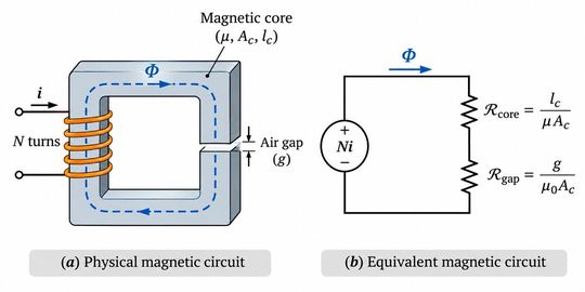
The (B)-(H) characteristic is a common way to show the magnetic properties of a core. At low levels of excitation the flux density may increase more or less in proportion to the strength of the magnetic field. However, as excitation is increased, the material approaches magnetic saturation.
Near and beyond the onset of saturation, an increase in magnetic field strength results in a much smaller increase in flux density. Saturation in an inductor can result in a significant drop in incremental inductance. As the incremental inductance decreases, a given applied voltage can produce a much faster increase in winding current, potentially overstressing the semiconductor switches and winding.
Another important property is hysteresis. The flux density does not necessarily follow the same path during increasing and decreasing excitation when the magnetic field changes direction. Instead, the material follows a hysteresis loop. The area enclosed by this loop is the hysteresis energy dissipated in the core per unit volume per cycle of magnetization. This loss leads to heating and affects the efficiency of magnetic components.
Magnetic materials exhibit different permeability, saturation, and loss characteristics.
The main families used in power magnetics are compared below. The values are indicative, since they vary with grade, temperature and measurement conditions.
| Material | Typical Bsat | Main characteristics |
|---|---|---|
| MnZn ferrite | ≈ 0.35–0.5 T | High resistivity and low core loss from tens of kHz to MHz; lowest Bsat, which decreases with temperature |
| Powder cores | ≈ 0.75 T (MPP), 1.1 T (Kool Mu), 1.0–1.4 T (iron powder) | Distributed air gap, low permeability, soft saturation and good DC-bias tolerance |
| Silicon steel | ≈ 1.5–2 T | High Bsat but low resistivity (laminated); suited to low frequencies |
| Amorphous | ≈ 1.6 T | High Bsat, lower loss than silicon steel |
| Nanocrystalline | ≈ 1.2 T | High permeability and low loss at medium to high frequencies |
Since
, a higher 𝐵𝑠𝑎𝑡 allows fewer turns or a smaller core for the same volt-seconds. In practice, however, materials with high 𝐵𝑠𝑎𝑡 tend to have lower resistivity or higher loss at high frequency, which is why ferrites dominate at high switching frequencies.
Therefore, selecting a core material requires balancing magnetic performance, operating frequency, flux-density excursion, and thermal constraints.
Why magnetic components generate losses
Magnetic components are not lossless. Their performance is affected by two principal categories of losses: core losses and winding losses.
Core losses arise primarily from hysteresis and eddy-current effects within the magnetic material.
Hysteresis losses are associated with repeated magnetization cycles. Eddy currents are circulating electrical currents induced within conductive core materials by changing magnetic flux.
These currents dissipate energy as heat.
Core losses depend on material characteristics, switching frequency, flux-density waveform, and operating temperature. For sinusoidal excitation they are often modelled by the Steinmetz equation
, where 𝑘, 𝛼 and 𝛽 are material-dependent fitted parameters (typically 𝛼≈1–2 and 𝛽≈1.5–3). Higher-frequency operation can make these losses increasingly important, even when the magnetic component becomes physically smaller.
Winding losses arise from the electrical resistance of the conductors.
When frequency-dependent effects are negligible, winding conduction losses can be approximated by:
where I is the RMS winding current and Rdc is the winding resistance measured under DC conditions.
At higher frequencies, however, the current distribution inside a conductor is not uniform.
The skin effect leads to the concentration of alternating current near the surface of the conductor, reducing the effective conducting area. The skin depth is
about 0.2 mm for copper at 100 kHz. The proximity effect occurs when magnetic fields generated by nearby conductors induce eddy currents and redistribute current within the winding.
Both can increase effective AC resistance and winding losses. In multilayer windings, proximity losses can be quite significant. Furthermore, the harmonic content of switching waveforms can
lead to additional high-frequency losses that are not accounted for by a simple DC resistance calculation.
A more accurate winding-loss calculation therefore considers the frequency-dependent AC resistance associated with the current harmonics.
Therefore, lowering the resistance of the conductor alone does not guarantee low winding losses at high switching frequencies.
Different magnetic components, different operating conditions
Inductors and transformers work on the same electromagnetic principles but are operated under different electrical and magnetic conditions.
The filter inductor normally carries a large DC current with a small AC ripple. Its magnetic design must be able to accommodate the resulting flux-density bias without saturation. Only the AC ripple, which sets the flux swing, produces core loss; the DC component produces none but moves the operating point toward saturation.
An AC inductor in a resonant converter can experience a much larger alternating current and flux-density swing. In these cases the losses in the core and high frequency windings can be the most important considerations.
A conventional transformer uses a common changing magnetic flux to transfer electrical energy between windings. The magnetizing behavior is mainly related to the applied voltage waveform (it is represented by the magnetizing inductance; flux that does not link all the windings appears as leakage inductance), while the winding currents depend on the connected circuit and load.
This distinction is especially important for flyback converters. Often called a flyback transformer, this magnetic component is a coupled inductor, which stores energy in its magnetic field during one switching interval and releases it to the output during another. In a typical gapped flyback magnetic component, most of the stored magnetic energy resides in the air-gap region, since
These varying operating conditions are the reason magnetic components cannot all be designed under the same assumptions.
Key questions
Why can a magnetic core saturate even when the winding current appears to be within its expected operating range?
Saturation of the core depends on magnetic flux density, not just the nominal current rating of a part. For an inductor the magnetomotive force is provided by the winding current and defines the operating point on the magnetic characteristic of the material.
For a transformer , Faraday 's law determines the change in magnetic flux with the applied voltage and the time over which it is applied . Thus, too many applied volt-seconds, the wrong number of turns, or an unexpected DC flux bias can drive a core into saturation. Saturation flux density also decreases with temperature (for the ferrite 3C95, about 530 mT at 25 °C to about 410 mT at 100 °C), and inductance tolerance or start-up and transient currents can push the peak current above its nominal value.
Therefore the operating waveforms and core characteristics relevant to the application should be examined rather than simply the current rating.
Why do magnetic components become more difficult to design as switching frequency increases?
For a given power level , increasing the switching frequency can reduce the amount of energy transferred per switching cycle . This can enable smaller magnetic components . However, the achievable size reduction is dependent on the converter topology, the magnetic design, and the operating conditions.
Core losses depend on the frequency and magnitude of the magnetic excitation . Skin and proximity effects increase the effective resistance of the winding conductors . Smaller magnetic component can also have less surface area for heat dissipation.
The design challenge is thus to give the required magnetic performance and at the same time keep down the core losses, winding losses, saturation and temperature rise.
Higher frequency can allow for greater power density, but does not necessarily lead to a smaller or more efficient magnetic design.
Conclusion
Magnetic components bridge the electrical and electromagnetic worlds of power conversion. Their behavior is governed by the relationships among current, magnetic field strength, flux density, permeability, and core geometry. These relationships explain how inductors store energy, mostly in the air gap when one is present, how transformers transfer energy, and why magnetic components exhibit saturation and losses. Before discussing practical design choices such as core dimensions, winding arrangements and material selection it is important to understand these basic principles. The next articles in this series will cover the use of these principles in the design of inductors and transformers for switching power converters.
References
R. W. Erickson and D. Maksimović, Fundamentals of Power Electronics, 2nd ed., Kluwer Academic Publishers, 2001, Part III: Magnetics, Chapter 13, “Basic Magnetics Theory,” pp. 491–537.
(ID:51013297)

