


:quality(80)/p7i.vogel.de/wcms/40/62/4062c2d596e53b038e0f05f6c3182509/0133843963v2.jpeg "Littelfuse introduces ultra-low-capacitance TVS diode arrays with a 6.5 V clamping voltage for transient protection in automotive and consumer electronics. (Source: Littelfuse)")
:quality(80)/p7i.vogel.de/wcms/e5/9e/e59ecc43d3c278aece316be4209113c9/0133732079v2.jpeg "Renesas introduces its first low-voltage GaN FET family, with 100 V devices for power conversion in AI data centers, robotics and industrial systems. (Source: Renesas)")
:quality(80)/p7i.vogel.de/wcms/c4/a7/c4a7243caa7c26af5fe5108f7894050a/0133626683v2.jpeg "Wolfspeed’s new premium 200 mm SiC substrates are designed to provide more consistent starting material for power semiconductor manufacturing. (Source: © Marina - stock.adobe.com)")
:quality(80)/p7i.vogel.de/wcms/91/8b/918b533161e7327075370338d7af97af/0133589801v2.jpeg "Acbel will present scalable DC charging power modules and an 11kW passively cooled 2-in-1 on-board power solution at New Mobility Congress 2026 in Katowice, covering both charging infrastructure and vehicle applications. (Source: Acbel)")
:quality(80)/p7i.vogel.de/wcms/4f/47/4f473b006be95fb33ec3d8e3fd727b06/0133732443v2.jpeg "SEMI Europe joins the European Commission’s STEAM Executive Panel, bringing the semiconductor industry’s skills needs into discussions on education, training and workforce development. (Source: © phonlamaiphoto - stock.adobe.com)")
:quality(80)/p7i.vogel.de/wcms/c4/59/c459b75bff747399a7a7fd58381f3983/0133731182v2.jpeg "Infineon has completed its acquisition of C2i Semiconductors, adding expertise in software-defined power management and multiphase control for AI data-center power systems. (Source: © InfiniteFlow - stock.adobe.com)")
:quality(80)/p7i.vogel.de/wcms/fd/2c/fd2c2388e7985cd4c75cff39f07f6361/0133676222v2.jpeg "Greenconn expands its connector portfolio with the compact WF28 wire-to-board series and new 25 mm and 30 mm stacking-height options for its GC01 floating connectors. (Source: © Greenconn)")
:quality(80)/p7i.vogel.de/wcms/69/06/6906b5f22bfbb3f8b874ba9e459c7d26/0133675448v2.jpeg "New backend manufacturing hub strengthens and further diversifies Infineon's global production network. (Source: © Apriew - stock.adobe.com)")
:quality(80)/p7i.vogel.de/wcms/b4/93/b493d5ce620cf7eb558ca6bcd9852a1e/0133811655v2.jpeg "The massive integration of utility-scale solar photovoltaics demands BESS platforms equipped with high-power-density inverters to mitigate generation intermittency. (Source: Pixabay)")
:quality(80)/p7i.vogel.de/wcms/f8/cb/f8cbf79cc21d48d7cad08e2b620218f7/0133738515v2.jpeg "Microchip and Navitas are demonstrating a 20 kW reference design that converts an 800 VDC data-center bus to a 6 V server rail, combining GaN power devices with digital control. (Source: © Formoney - stock.adobe.com)")
:quality(80)/p7i.vogel.de/wcms/ee/de/eedef7055c094757eb208a9d181e85dc/0133371000v2.jpeg "Resonac has developed 300 mm SiC single-crystal substrates, advancing larger-diameter wafer technology for next-generation power electronics and other high-performance semiconductor applications. (Source: © Resonac)")
:quality(80)/p7i.vogel.de/wcms/7b/76/7b76005554b556df2a7a3794bdf69d44/0132365246v2.jpeg "Hioki’s ST5680A DC Hipot Tester combines CE/UKCA/CSA compliance, an integrated capacitance‑based contact check and time‑series waveform recording (voltage, leakage current, insulation resistance) to standardize hipot and insulation testing across EV cell, module and pack production lines. (Source: Hioki)")
:quality(80)/p7i.vogel.de/wcms/af/7f/af7f7b0fb7f29219fc991b1130f65477/0132241333v2.jpeg "Comprehensive laboratory testing regimens—combining thermal cycling, high‑current stress, EMC, and accelerated lifetime tests—are essential to validate advanced power designs and ensure reliability in real‑world applications. (Source: PRBX)")
:quality(80)/p7i.vogel.de/wcms/16/3d/163df69363f8125315a9826e13ea4b05/0131927425v2.jpeg "Solution will maximize data center and AI factory profitability while delivering engineering-grade insights to design and operations for more efficient, sustainable, and resilient infrastructure. (Source: Cadence)")
:quality(80)/p7i.vogel.de/wcms/85/b7/85b7e90733a2bd8f21515d8f7137f2fc/0131917677v2.jpeg "Renesas acquires Pictorus to integrate its embedded application software platform with Renesas’ MCU and MPU portfolio, helping developers shorten time‑to‑market and simplify system integration. (Source: © lucadp - stock.adobe.com)")
:quality(80)/p7i.vogel.de/wcms/27/07/2707280c807689b437baed3660257404/0133626052v2.jpeg "The quantum behavior of electrons shapes semiconductor devices—and the power converters that deliver electricity to modern computing systems. (Source: © Celt Studio - stock.adobe.com)")
POWER DELIVERY Protection and telemetry in AI with 800 V hot swap
Related Vendors
:fill(fff,0)/p7i.vogel.de/companies/63/c7/63c7da97be945/diotec.png "diotec (Diotec Semiconductor AG)")
:fill(fff,0)/p7i.vogel.de/companies/68/2c/682c3e2e9a195/logotype-rvb.jpeg "logotype-rvb (MERSEN France)")
This article addresses the growing power demands of AI server environments, driven by the increasing power consumption of GPUs. It highlights the shift from 48 V to 800 V power delivery architectures and explores engineering approaches to high-voltage hot-swap protection as data center infrastructure evolves.
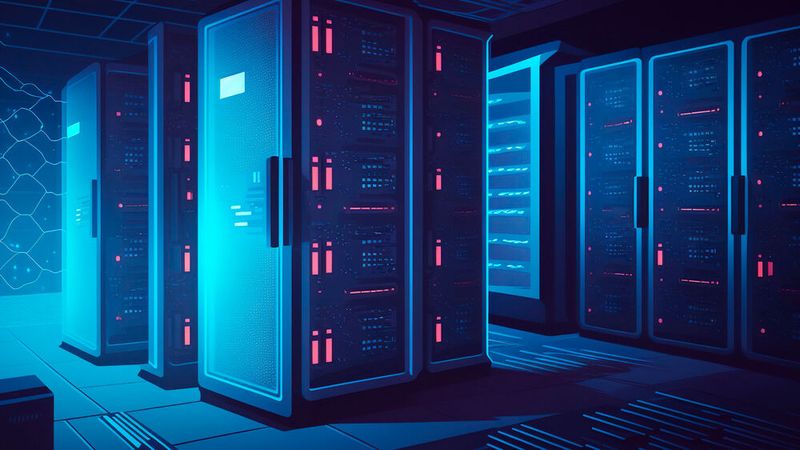
As AI workloads intensify, GPUs in server environments are driving unprecedented power demands—prompting a shift toward an 800 V power delivery architecture at the rack level. This elevated voltage introduces new challenges for system protection and monitoring, particularly during live tray insertion and removal. To address these challenges, next-generation hot-swap controllers are required to manage high-voltage inrush currents while providing robust telemetry for system diagnostics and safety.
Why does 800 V matter?
Two key trends are driving the transition to higher voltage power delivery at the rack level in AI server infrastructure.
1. Rising GPU Power Consumption: As GPUs continue to scale in compute performance, their power requirements are increasing significantly.
2. Higher Compute Density per Rack: To maximize performance and minimize interconnect latency for large-scale AI training and inference, more GPUs are being consolidated within a single rack. This co-location improves bandwidth efficiency and reduces communication overhead by shortening data paths between accelerators.
To meet the resulting surge in rack-level power demand, the industry is moving toward a disaggregated power architecture. In this model, traditional power components such as power distribution units (PDUs), battery backup units (BBUs), and capacitor units (CUs) are relocated from the main IT rack to an adjacent power sidecar. This separation not only supports higher voltage delivery, such as 800 V, but also frees up valuable space within the rack for additional compute resources.
:quality(80)/p7i.vogel.de/wcms/9e/b0/9eb01567f828f28e7922897edc690be2/0130454119v2.jpeg "Voltage drop is a result of current flowing through a resistor. (Source: © Viktor - stock.adobe.com)")
RESISTOR CALCULATION
How to calculate voltage drop across a resistor?
The existing approach to power delivery
AI racks operate with a 48 V busbar (Figure 1). AC is converted to 48 VDC using in-rack power supply units (PSUs). The 48 V bus feeds IT equipment (server PSUs, GPU nodes, switches), BBUs with their own bidirectional DC-to-DC converters, and supercapacitor units (SCUs) for fast ride-through and transient handling.
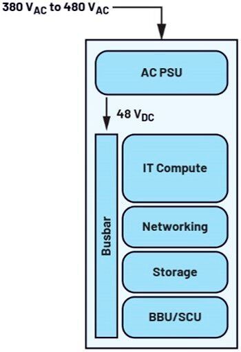

Each node on a rack (for example, a server tray) requires the capability to be switched in and out during live operation. In practice, service technicians replace servers via hot-swapping, allowing them to remove a node, swap it, and push it back in without shutting down the entire rack.
During this event, the node’s hot-swap controller disconnects power internally, allowing the node to be removed safely. The rack’s busbar stays energized and continues feeding all other nodes, BBUs, and SCUs. Once a replacement node is inserted, precharge circuits limit inrush before full connection, a key function of the hot-swap controller. The node then boots and rejoins the AI cluster automatically.
Figure 2 shows the power distribution of an AI server from 48 V busbar to processor. The hot swap controller is clearly shown as the first interface to allow the technician to safely and efficiently remove the node.
Evolution to higher voltages
With the increased power load from AI processors, a new horizon in higher DC voltage distribution to the rack is emerging. ADI is on the cutting edge of these solutions and working closely with industry leaders to solve such problems.
A new voltage distribution domain is defined to the rack—800 V. This is fed from a sidecar directly to the IT rack. Figure 3 shows the proposed architecture.
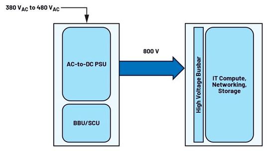
The primary driver for transitioning to higher rack-level voltages is the escalating power demand per rack. As power increases, so does the current flowing through the busbars. This rise in current necessitates larger and heavier busbars to maintain acceptable thermal and electrical performance—posing significant challenges in terms of mechanical practicality and system design. By increasing the delivery voltage, the required current can be proportionally reduced, enabling the use of more compact and manageable busbar dimensions and interconnects. This shift to higher voltage is essential for maintaining scalable, efficient, and mechanically feasible power distribution in next-generation AI server racks.
It’s worth noting there can exist intermediary steps in this architecture evolution where a 48 V busbar is used in the rack. In this case, PSUs are scaled to higher powers, accepting 800 V at the rack and downconverting to 48 V to marry with existing busbars. However, this is not a longer-term state as power will be limited (maybe up to 250 kW per rack) and the goal is to allow for maximum compute capability in a single rack, driving power to 1 MW per rack by the end of the decade. PSUs and BBUs are therefore best positioned outside of the IT compute rack, as shown in Figure 3.
In the future, solid-state transformers are likely to be used to distribute high voltage directly to each IT compute rack without the need for these sidecars.
:quality(80)/p7i.vogel.de/wcms/f7/29/f729bd8948948e6d9149cbc59983cab4/0129779015v2.jpeg "Bourns expands its surge protection portfolio with high-energy GDT devices in a compact package. (symbolic image) (Source: © Jack - stock.adobe.com)")
POWER SAFETY
Bourns launches compact high-voltage GDT surge protectors
Taking hot swap to the next level
Designing hot-swap protection for 800 V architectures presents several distinct technical challenges that must be addressed:
Power Density: This is a critical factor, as the 800 V hot swap circuitry ultimately resides on the server card within the IT rack. Space on these cards is highly valuable and will face growing constraints as rack densities increase, fitting more servers into each rack. As a result, high voltage hot swap solutions must be designed to occupy the smallest possible footprint.
High Voltage Control and Protection: Transitioning to 800 V introduces significant safety challenges. While 48 V poses minimal shock risk, these higher voltages can be life-threatening. Consequently, hot swap circuitry must handle large current surges within microseconds, making precise control essential. Managing the inrush current ramp is critical to avoid damage to the rack or harm to technicians. The system must also coordinate timing, detect overcurrent or undervoltage events, and shut down gracefully when required.
Telemetry: As the first component in the node’s power path, hot-swap controllers are positioned for data acquisition. They must precisely measure voltage, current, and power while logging events such as overcurrent, undervoltage, and thermal shutdowns. In addition, reporting temperatures from the power switch (MOSFET) or nearby PCB areas delivers value by enabling real-time load current profiling, which improves energy demand forecasting and supports predictive maintenance.
Component manufacturers are actively developing high-voltage hot-swap controller solutions to address these emerging architectural requirements, focusing on compact form factors, precise high-power control, and enhanced data acquisition accuracy.
Conclusion
This article highlights the critical shift toward 800 V power delivery in AI server racks to accommodate the increasing power requirements of advanced GPUs and support higher compute density. The new architecture involves moving power components to a separate sidecar, optimizing space for compute resources in the main rack. Next-generation high-voltage hot-swap controllers effectively manage inrush currents, offer comprehensive telemetry for system diagnostics and safety, and ensure reliable operation in high-voltage environments.
About the author
*Donal McCarthy is a marketing director at ADI focused on data center power. Donal holds a B.E.E. from University College Cork, an M.B.A. from Boston College, and a marketing diploma from the Irish Management Institute in Dublin. Donal’s held various roles including design engineer at M/A COM, field sales engineer and marketing roles at Hittite, and marketing management and director roles at Analog Devices.
(ID:50846966)
:quality(80)/p7i.vogel.de/wcms/94/ad/94adeaeec77b29a3b7686c34ee304809/0133333835v2.jpeg "AI data centers are moving toward 800 VDC distribution and megawatt-scale racks, creating a new power architecture in which SiC and GaN technologies serve different stages from the grid connection to the GPU. (Source: © Ahmed - stock.adobe.com)")
:quality(80)/p7i.vogel.de/wcms/34/19/341939fbe8f9088c6c357433b2383281/0132720702v2.jpeg "Wolfspeed and LITE-ON partner to develop 800 VDC power solutions for hyperscale AI data centers, leveraging silicon carbide technology to improve energy efficiency, reduce thermal stress and handle surging AI compute loads. (Source: © Javed - stock.adobe.com)")